Wednesday, November 26, 2014

The KF7DFP VTTC PICS --NEW PICS--

A quick shot of the corona, the area where plasma is produced very quickly.  I was amazed to find that the plasma dissipates and is produced very quickly.  One photo in this sires was taken at 1/400th of a second.  High speed video proves that the plasma changes very quickly--faster then ~1/120th of a sec. or so but is changing constantly.  Every photo is different and changes to the circuit can produce different corona and sprite possibilities.  The plasma appears fully in less then 1/100th of a sec. and it disappears in less then 1/60th or so from other tests.  This article is still in work on so sorry about some of the spelling and other errors.


 The finished KF7DFP VTTC.  I call it the VTTC1200.  This is a project I've been putting off for a long time but finally got around to doing.  It took me about 2 days to wind the secondary, which can actually be removed and replaced with another type or coil.  This is a very useful and interesting feature I thought to add. Not only does the beaker provide insulation, but also allows me to actually swap out secondaries to see how they respond.  There are limits, but other secondaries with higher turn counts may be possible.  This is a pretty dense hand wound coil, #32awg. I think there are about 3-5000 turns.  I have not made a good estimate.  Most of the energy is produced in the lower half of the coil where flux density is highest.  


I've built several classic Tesla coils and smaller units, and even a "pulse coil" which ran on about 30kv.  The photo on the top of my blog was taken from the pulse coil system.  I decided to try a TV flyback before I got an NST. The NST version is on YouTube, I may also have the pulse coil on there too) channel="mostlymacros".   It worked, but the output is intermittent and like all coils that use a spark gap-- really messy.  My first SSTC design which I will publish here later was a success and stable, but not very powerful and I had problems keeping the single mosfet cool.  I built it about 2 years ago.  I have the components to do another SSTC and probably will eventually do something using a PWM and some kind of push pull mosfet drive. There are advantages that tubes have for some circuits over solid state however.  So then again--if I can find some of the types I need--I might just stick with tubes. Tubes have properties that are very resilient, not to mention really good sound so they are making a comeback! Tubes or thermionic "valves" have some pretty amazing properties.  I chose to use a tube because of the overload capacity and flexibility. I have made it a point to study tube design.

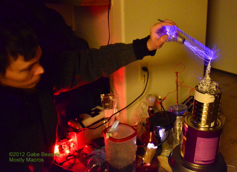
Sometimes I catch the plasma going straight up into the air in two lines mostly. Other times, I catch it just as it powers up (as seen here) and just after it shuts down as the plasma dissipates.  Here, the initial surge can be seen in the large arcs that begin to form the cycle of oscillation. This is a frozen very short moment in time, most of these pics are not long exposures.  They are actually settings not un-common for an overcast daytime shot.  I kept my iso pretty high, just so that I can catch clearly the sprites that emanate from the plasma and bolts of electricity here.  This coil from top to ground (across secondary) produces about 80-110kv peak.  I may be able to reach 120kv, but I think I'm closer usually to 90kv.  If you go by 1.1mm=1000v then I've got 100kv and more.  I tend to think at 200ft above sea level this rule does not do so well, it seems more like 1.5mm per 1000volts.  Measuring voltage by arc size is an old and difficult method that is often unreliable.  However, provided your not too high above sea level, and that your under pretty typical conditions, an arc test from point to point in open air can give you an idea of how many volts you have.  You can find out for sure approximately how many volts, DC or AC you have.  However, in order to do this, your current must be high enough to be visible and this voltage must be able to create a visible arc in the air as the electricity jumps.  What often people don't know, is that electricity does not just jump from point A to B via conductors like metal.  It can travel when highly charged and/or as AC--through the air invisibly.  If you took 1000 batteries and tied them together, just hooking up a loop of wire connected to nothing on either end of them would produce a small spark (arc) and momentary radio signals!  Even though, apparently, there is no visible complete circuit.  This is due to capacitance and electrical fields in the air.  A coil of wire is usually seen as an inductor, but when it is connected to but one electrical pole, it acts as a 'lump' of capacitance. The charges trying to equalize, a spark is produced when something is "bonded" to it.  It looks like free energy, but it's an electrical field that if one did this dangerous experiment, you could hear as static discharges in the battery pile. As can be seen here--it can also jump seemingly into nowhere.  But this is because charges travel through the air without being visible.  The heat that ionizes the air and burns it out as far as the power will allow in this coil. After a certain point and the circuit is completed by capacitance of electrical field in the air itself.  This is why a screw driver connected to nothing will illicit a large arc--bigger then that seen in large flyback drivers!   I have built big kv meters, (Up to over 250kv) but calibrating it can be difficult since finding a meter that can measure over about 50kv--is very difficult and expensive.  So I used a number of tests to calibrate mine.  For this coil, I generalized my location and other tests to come up with the ~100kv or so safe output max.  If too much energy it put into the supply, either the tube will overheat or the coil will begin to arc on itself, so this is the limit for both this coil and the tube that powers it.  The voltage is AC of course and radio frequency and thus we get the great coronas and sprites out of the top, they are incredible like unpredictable sculptures.


I started doing tube experiments as well as plasma tries with transformers and Model T Ford coils when I was about 11.  The first real assignment with tubes I gave myself was to transpose simple circuits like a Hartley oscillators into tube forms from solid state circuits.  In that case, a center tapped coil and variable capacitor for tuning.  With a little math, the tank circuit resonant frequency can be figured out.  Thus I was able to begin to build radios that listened or transmitted where I wanted them too!  Then I moved into experimenting with other devices. Tubes are very forgiving within reason, and if something goes wrong you far less likely to lose the tube then an expensive mosfet.   You can see what's going on inside, and keep an eye on things, they also are really tough--I've seen tubes get so hot they glow entirely across the plate but when cooled back down--they still ran fine again.   I even pulled a few tubes out of an old TV that had been laying in the bushes for decades in Guam, fired it up and it worked until a typhoon wreaked my place and I lost most of my stuff.  Years of harsh rain and sun did nothing to damage the glass sealed device. As fragile as they may be in shipping--they are really tough compared to the mosfets and transistors that replaced them.  Tolerances can be looser, substitutions simpler, and some kinds of circuits just work better and can have a lot less components if built with tubes.  Tubes have a lot of gain and bandwidth--the only thing that comes close to them in solid state are mosfets and a few other emerging technologies. The military is interested in tubes since they are virtually EMP proof. Russia kept making all there radios for fighter jets out of tubes at least into the 1990s for this reason.  And for sound quality there's no comparison according to many, myself included, who say tubes have the best sound in the world for audio gear.

In 2010, I shattered my myth about tube plate voltage since every book I read talks about how important B+ needs to be pretty high voltage.  Never under 45volts.  I was able to power a 12AX7 tube oscillator with just 15volts!  That's right, it was actually possible to get a sine wave and tune a tube Hartley tank circuit that had a plate voltage of only 15 volts.  The circuit was built in a cascode fashion, which means that one triode was driving modulation into the 2nd triode which was an oscillator.  Plate into cathode from triode 1 to triode 2.  The 1st tube lost it's bias with audio and sound quality around 30volts or so, but the CW signal and sine wave remained strong and could be turned on or off at will with a plate voltage not much more then 12 volts! I could have used it as a local oscillator for a receiver.  I never thought a tube circuit could run at such low voltage.  The filaments were actually running a bit lower then specs, but electron emission can happen to the plate for an oscillator at very low voltages. I plan to do some more tests with this, this is especially true with smaller high gain signal tubes.  In most literature about tube design--45volts is as low as you can go.   I wonder what else you can do with them--cold cathode?  Some tubes do operate if you use enough voltage--such as magic eye tubes and even TV CRTs-- but space charges and other issues get in the way of grid function so they are not good for much without a hot cathode unless they were designed for a particular function like a plate relay control.  You can create wideband noise out of a gas discharge tube, or use one to turn a plate relay on and off.  But if you want audio frequency amplification, gain and any radio projects--you pretty much do have to keep your plate voltage (or B+ battery supply) above 45 volts and towards the tube's intended voltage and filaments/heaters must be hot enough for the electrons to begin to "boil off" so that they can be grabbed by the plate.  But they are very flexible as far as design goes and just how far you can push them. I have not posted my SSTC design yet, but I will say it is the simplest one I have ever seen.  I was able to build a pretty good SSTC from a 555 timer chip by feeding just enough power back so that it became a resonant circuit through the timer.  A strange and unusual way to use the 555 chip that I just decided to try, and it worked well with large mosfets like the IRFP260/460.  The timer is basically a PWM, and when it has almost no timing capacitance on it--it will still oscillate!  I found that they can go into several hundred Kc, so getting up to the resonant frequency of a air core primary was possible.  I protected the mosfet as I always do with several parts, and the timer need only 50ohm 1/4W resistor and 0.47mfd capacitor or so to drive the gate and insure that the chip never gets totally shorted if something happens to the mosfet. I did not however get nearly as much power out of it as I do here with the tube system. And the mosfet was in constant danger of overheating or being damaged.  Tubes are almost immune to this kind of transient high voltage and they can overheat, but you can monitor this if your using glass tubes. This makes them ideal for power RF amplifiers or Tesla coils that would have to be far more complex and/or expensive if done solid state.  The corona on my SSTC was only about 1-2inches long and the mosfet was under a lot of pressure for many reasons so I could not run it for very long without letting it cool.  I really had to only run it for a few seconds at a time but it was a stable viable circuit that I built twice. The corona on my VTTC here is about 4-5 inches with sprites up to 7+ There are many great SSTC schematics online, the concept is pretty simple but coil building and winding is difficult work sometimes since there are so many possible problems with arcing and induction that must be addressed.  I did not find such an abundance of good VTTC schematics, but then again I did not look for very long.  I designed this circuit myself.  When I did finally check out other schematics online, I found many VTTC schematics to be pretty low-powered. This may be because the volts needed at currents this high are VERY dangerous.  At 1000volts 2amps or so, you really don't get 2nd chances.  And to run a larger VTTC voltages quickly get into the 2000+ range at 1 amp or more.  The means of doing this is so dangerous that I hesitate to post it.  You don't get burned, you don't get shocked--you get electrocuted!  Lights out.  The general voltage for the electric chair in many states was 2000volts at 2-4amps AC. I don't think I need to say more about why this is so dangerous!  MOTs are very dangerous and often underestimated, this is why microwave ovens are setup so you cannot use them with the case off.  The transformer core is one side of the 2000volt secondary and they are capable of producing 2kv (2000volts) at as many as 2-5amps if the electrical outlet powering them can handle it.  I may need to use a 2 phase (240volt) outlet for my next VTTC as I will need a really big voltage.  So safety is very important with VTTCs.  There are tube transformers out there that can produce about 1200volts or more and can be found online in different places.  Lots of old radio and other gear use them. The other way is to build an inverter supply that will convert 48Vdc volts into 1200volts at 1 amp or so at higher frequency--which makes it safer if it's up in the 10kc or above range--but still very dangerous!

I have also seen people using a MOTs to ballast another MOT.  A bad idea.  A shorted MOT pulls so much current (more then 15amps at 120vac) that using one as a ballast will do almost nothing for keeping current down or reducing voltage and danger.  It's pretty much equivalent to using a wound up 30ft extension cord as a ballast. You can still get almost as many amps through it. MOTs are high-current specialized transformers that generate a great deal of magnetic flux, so much you can feel it with any metal near by.  The primary is only about 130 turns or so if I recall, #10 or 12 AWG solid--this is really big wire for a primary and produces a very large magnetic field.  The secondary is #28 or larger AWG so the current you can actually get out of a MOT far exceeds the 15amp limit on most home outlets.  In a microwave they push it as far as about 1300watts.  That's almost 11amps.  These are so powerful that if you shorted it you'll be drawing something like 30amps from your outlet and most certainly kick a breaker off or blow a fuse.  If not, the arc becomes very dangerous because it's energetic and large--not something to try, seriously.  To ballast a MOT for less power, use an auto-transformer or a series of 100W incandescent light bulbs in parallel and then in series with the primary. This reduces current to reasonable levels that will not blow breakers or cause dangerous flash-arcs.  It's still very dangerous, but if anything happens the excess current will light up the bulbs instead of running the MOT.  The same can be done with other types of large tube transformers that may also produce high currents in similar ranges.  You can see the idle current in how bright they get when it's on, as well as how much your using.  It also helps to put about a 6-10uf AC capacitor on the primary, this reduces the impedance of it and lowers the idle current. If a MOT is left on without an AC cap, it will get quite hot eventually even if not pulling any load.  Not to mention that left idle, a MOT can pull as much as 1.5amps or so at 120vac.  That is enough to run a big TV.

  I recommend an insulated remote momentary only switch as I did here that cuts all power to such a HV transformer virtually instantly.  With the big tube transformers--you don't get a 2nd chance.  These shocks are almost as serious as touching an industrial power line. There are some really great VTTCs shown on YouTube, some very powerful transmitting tubes and coils.   A lot of watts are needed no matter how you do a VTTC/SSTC.  My SSTC used 90volts out of several power supplies in series. I only built a prototype and never did build a permanent version of the circuit, but for a beginner coil builder who wants something simple--it would be a great start.  So I will post it here soon once I draw it up in digital form, it's only in my notes now.  It is easy to power with a 5A auto-transformer.  A better source then a series of transformers.  Under it's requirements, the voltage dropped to only about 50volts while it was running.  The load on my 4amp laptop DC supplies and others together really was hard on them as well.  I just bought an auto-transformer and put a bridge on it--creating a DC power supply.  One can filter this and make it really nice, you can select your voltage and use it as a kind of "brute force" supply.  There will be a drop in the voltage but compensation is as simple as turning it up at bit more.  Auto-transformers make great power supplies since they give out even current from 2volts or so all the way to 120 or in some models, 140volts.  They also are built in a way that accidental overload or over-volt is very unlikely since the dial must be turned for the transformer to use more power, and it's a pretty big dial. So you can trust that it won't short and suddenly dump 120volts into your circuit that can only handle 40V!  As is the trouble with using a load and light dimmer for such a supply.  The SSTC I first built did however let me show some of the fractal effects of plasma and arcs.  How one AC arc can form a sprite on it's own.  I dubbed this effect "arc flares".  The coil here produces a fractal of plasma reflecting complex components of the AC/RF and the DC used to power it.

The isolated remote also acts as a key and is powered by the filament supply transformer.  It uses an SMA connector to a small switch I can hold in my hand for photos.  Don't want to get too close to this thing with a camera though!  The switch controls the HV transformer with a microwave oven relay. I also use an AC capacitor to reduce relay arcing.  The plasma draw comes out of a removable crossbow bolt tip. 


A sealed jar becomes a pressurized chamber and then a partial vacuum when plasma is released into it.  This is really amazing to watch, I can create all kinds of effects in the jar. Smoke gets obliterated, and gasses in the air from the smallest things cause changes to the corona.

 The wave function is clearly visible in many photographs taken at about 1/20th to 1/10th a sec.  This one was at iso800.  Some pictures show very clear 3d sine waves.  I have many more taken with a full frame camera that will soon be posted. This is as close as we can get to actually seeing a radio wave.  It is not the actual wavelength of the coil but rather a product of a series of functions in the circuit.  Basically, the closest simple analogy I can think of (albeit not entirely correct or comparable) would be to compare this effect to a guitar string that has been plucked and then rotated from the bottom at another frequency a full 360 degrees. It also kind of comes up out of the coil like a spring and gets recorded as it forms in the air on the camera's sensor. We see not only the plasma being produced now, but the plasma flowing off that is dissipating as other sprites start.  The cycle happens very fast. Three frequencies are important here along with there harmonic components.  300khz (300kc), 60hz and 120hz from the diode bridge HV power supply.  The plasma actually forms by building up as heat increases in the air. The arcs form sprites at semi-regular intervals. A number of variables exist here, but we are most probably seeing mostly the 120hz wave form in these sine wave sprites. We are also possibly seeing the difference between 120hz and 300kc. =2500hz, and of course the 60hz ripple as well. When a DC circuit has an AC component it's called "ripple".  A set of electrolytic capacitors and filter chokes would eliminate these, but after running this unit with them and without them, I found allowing quite a bit of ripple here to be a good thing.  It produces very interesting fractal paterns based on the many sine waves produced here.  So in effect with a camera we can stop it fast enough to see the waves in action.  The sweeping motion however is also there and visible to the naked eye but very fast.  The corona is just as large as seen in this picture here, this is not a long exposure or something to make effects more dramatic.

RADIO RFI -- and PICTURES of wave function:
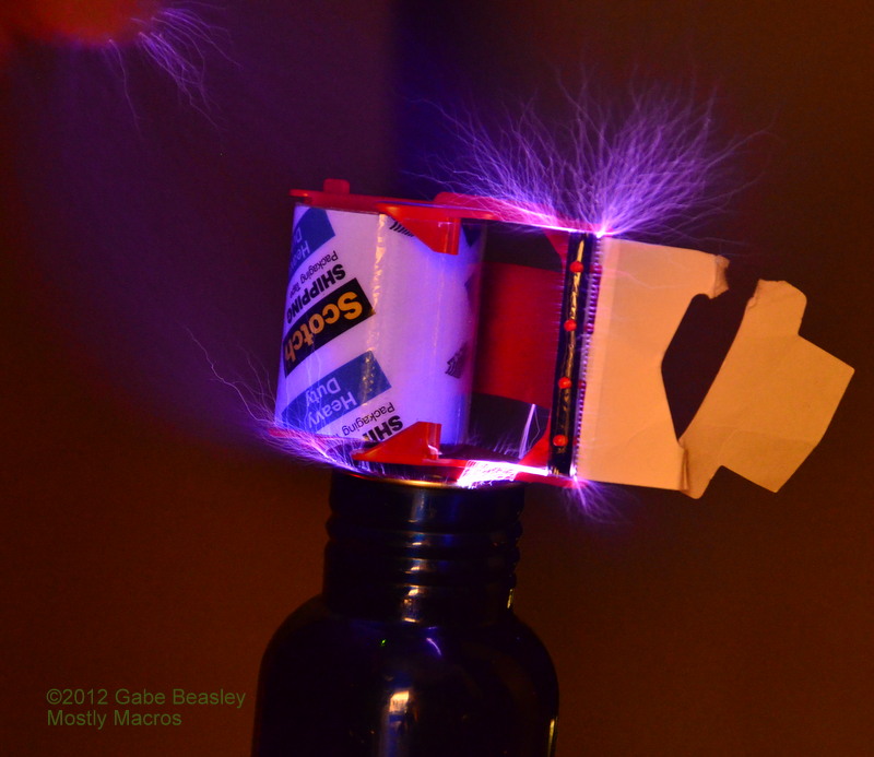
So the wave we see most often in the coil is the 120hz and then sweeping at 300kc  (300,000hz). This is the fundamental frequency of this coil. It also has many harmonics as does any oscillator so for more powerful coils, especially if your going to use it for long periods of time you should be careful to filter the 120AC line.  Especially if your going to hook it to anything like a wire.  This is a very powerful radio transmitter but lacking a matched antenna, unless you live near an airport you should be fine.  I often operate it late at night and check how much I am creating harmonic RFI in broadcast band areas.  Also, keep all electronics away from such coils!  This thing can scramble the circuits on just about any digital device from several feet away!  Filters on the 120V AC side can reduce the amount of RF that gets back into the power grid without diluting the DC ripple effect.  A bifiar wound toroid would also work to modulate the grid if enough power was used, thus it could be modulated either via the grid or even possibly the cathode with a good enough driver.  Filters are a good idea for large coils to reduce harmonics from being transmitted as radio interference. Since we are at 300kc, we are also harmonically putting out quite a powerful signal in the AM broadcast band (530-1700kc) and down into the long wave spectrum where a lot of Navigational beckons are. So keeping leads short and not using any long wires is a good idea.  Don't send any Morse code!  So once again, basically I deliberately allowed 120hz/60hz into the coils plate supply.  The first design used a bank of capacitors and a 60hz filter choke, I quickly found that adding a bit of line frequency 60hz was good for creating large sprites and integral frequency effects. This is complex AC theory.  Components of 120hz/60hz and 300hz+ are allowed into the oscillator and thus show up in the plasma sprites (the largest arcs visible) 'painting' an image of an actual waveform.  This allows you to see the wave function exactly how it really is.  In 3d.  I've never seen this done before. I have seen other great coils, but seeing waveforms in the arcs I never noticed.  You pretty much need to take a picture of it at normal speed to be able to see it long enough.  Many of these shots were done at 1/120th a sec.  Most of these pics are not long exposures. Above you are seeing what it actually looks like in real life.  You can see the same thing by freeze framing an HD video of it. Most cameras shoot at 24-30fps.  More professional cameras can go beyond that into 60 or more FPS so that slow playback is possible.  This is very useful since we can see one event in 1/60th of a second which is exactly 1 cycle of 60hz. I was amazed when I captured it for the first time.  This is NOT my best picture example--more are coming of this effect including the fractal pics that show some incredible images in them with even more detail then these.  I have at least 5 more to post.  It can take dozens of photos to get a good wave picture. 


This was a longer exposure showing about 1sec if I recall.  That is why the neon power light seems so bright.  But you don't need along exposure to see the plasma as you can tell from the videos in the next article down.  The coil is finally finished, I have everything worked out so that a number of
different tubes will operate it.  Some more common then others. You need a pretty big pentode power beam tube for this. The 6KD6 tube, a large TV horz. tube, was able to run this coil but got a bit too hot. Only for short times if you use that type of tube since the plate may become too hot. I'm using a larger type, the 27LE6.  For looks, I moved the meter to a better spot on the board on the panel's right side. It does not directly reflect plate or grid current, measurements are really difficult since there is so much of an EM field.  It is an overall circuit current meter.  I know what the reading should be depending on how far up I dial the power.  So if anything is wrong I can tell if it is drawing too much power or not enough.  I can also get some measurement of the oscillator's current efficiency and how well matched it is. If too un-matched, the oscillator will lock up or go into a really high frequency mode that is very hard on the tube and produces no arcs.  The circuit includes a tuner that matches the primary so that loads on the secondary will not cause problems with the oscillation process.  This is basically the same thing as SWR with a radio, there must be a good load on this--or it will pull more power and heat up the tube's plate.  If this got too out of hand the plate would literally start to glow red, but that does not happen even under a lot of load. A circuit breaker prevents more then about a 1.5amp load.  As long as I match it with the delta IE control--I can connect it to anything I want such as the experiment with the jar where the plasma flows down into it.   And as I said already, I importantly added a remote control switch so that I can turn the coil on/off very quickly and without fear of an RF burn or shock.  Touching ground or grounded metal switches when this is on can cause RF burns if your close to the coil.  So an insulated switch is important. The tuner does not effect frequency much, the air variable instead controls coil load impedance matching.  This makes it possible for me to connect the coil to items and experiments without oscillator problems.  An important idea for my design since I wanted to do many experiments with this.  I'm sure other people have come up with the same concepts, but this schematic and coil design is my work.  The schematic is available on request only, since this is a very dangerous project and I want more people who view my site and write comments! Please subscribe and more projects will be posted.  Questions and such are always welcome, give me time to respond since I don't check my email all the time.

Turning up the power to over 1200volts on the plate, this coil can produce a lot of plasma.  I can even use it to cook things such as roasting marsh mallows and other items, plasma is a lot of fun and at 300khz--I don't have to worry about ozone production under most conditions since a "clean" AC VTTC or SSCT will produce very little of it even if large arcs are drawn. I have not even smelled any from this coil.  Getting exact measurements of current/frequency in the circuit is difficult however since there is so much RF present many devices don't work.  Even analog meters have problems due to EM and flux densities close to the coil!  I have estimated that the coil uses as much as 400-500W at peak operation.  It's output being in the 200-350W range.  I can safely (for the tube and other parts) only turn it up to about 1200volts at 1amp before I am in danger of completely overloading my tube and the auto-transformer that controls power.


60hz/300khz or 120hz/300Khz? --both--More about the ripple effect
As I explained above already, since I used a diode bridge in the plate B+ DC power supply design, we are getting a 120hz ripple in the DC output.  Basically, when you power a diode bridge with 60hz AC, you will end up getting AC components out of it if you have little or no capacitance on it or you draw so much current that the capacitance you do have cannot compensate.  Since a diode bridge will allow something DC powered to operate with current in either direction, when you change directions 60 times a second, it becomes a pulsed source of DC that is 2xF(ac) 120vac 60hz. I can't write much of the math here, I will just explain as best I can.  So in addition to RF AC harmonics from the oscillator, we have a 120hz signal--2x60 here. This is because each cycle either way has a phase change interval.  It is difficult for me to explain in detail here, but this translates to a 120hz signal in the DC if your power supply is full wave.  Most are, two diodes or a diode bridge will produce this effect.  I am just learning the complexities of AC theory and AC mathematics here myself.  So I hope I am correct in this theory.  It is also based on multiple scope tests. If you are powering something that uses lots of current but as I did here with only a small capacitor (in this case a total of 4.7uf) you will end up getting components of both 120hz and 60hz in the output.  Mainly the diode bridge produces 120hz if little or no capacitor is used of current drain is so high the capacitor can't keep up.  Thus, the frequency is multiplied once the diode bridge is under load.  We can even see this with a frequency counter if placed near the bridge or connected to it.  Since we are using really high voltage here--you want to be sure your meter can handle it.  I have a CatIII which means it's rated for 1000 volts.  Any more could damage the meter, but since the voltage is so high--we can keep the coil and tube off with just the transformer and supply idling and pickup the signal of both 60hz and 120hz from the supply.  120hz will be prominent on the + side of the bridge.  Basically, we have a couple of sign waves that overlap to produce the waveform pics. There is also a question of timing.  How fast does the effect get created?  The plasma stays in the air after the coil is off but only for about 1/120th of a second or so..  I deliberately kept capacitors low and used no DC filtration for these frequencies so that the supply would make a 'messy' output.  This produces really big sprites when ever the two fundamental sine waves converge with 120hz.  I would say it's 120/300000 or basically, a 2.5kc (2500hz) difference exists between the coil's fundamental operating frequency and 120Hz.  The AC main 60hz frequency will also have something to do with these incredible visible wave functions.  There are many factors that come into play here, it's a complex situation but what results is a fractal series of sign waves and plasma effects from the output tip, which is an AC load via capacitance.  When photographed at high speed with my full frame camera, it is possible to see just how amazing these effects are and even measure them since I can set my exposure time exactly.   Many more and better photos will be posted soon.


Wednesday, October 22, 2014

The Quad Flyback Driver --200KV from color TV flybacks!

Ok, Here it is, I will post still pics later.  This is a 200kv DC generator that uses 4 color TV flyback transformers in series.  There are NO voltage multiplication circuits here.  It is powered by my homemade CD-707 lab supply using a 1200W mosfet, IFXB100N50.   It uses a lot of power and I am pushing the limits of flyback design here.  I used to think 2 flybacks were a problem!  Four of them was more then a challenge. Put in oil, and with enough insulation and testing, this circuit runs incredibly well.  It is important that the driver can be tuned, and all primary windings are done in the same direction.  Also, very large wire must be used--HV TV wire--even in oil, 200kv will arc through almost anything.  I burned out a lot of wire before I found one that can handle it.  It runs on about 22volts at 7.8amps (about 170W).  Care must be taken not to overdrive the flybacks. A long in-oil capacitor bank prevents punching too much power through the integral flyback diodes and helps collect peak voltages.   The voltage can arc over 7 inches!  It might be possible to do more, but after a certain point the voltage on one side will probably blow through the flyback's insulation even in oil.  So using more flybacks in this way may not work long, even in oil.  To my knowledge I am the first person/lab to ever put 4 flybacks directly in series secondary connection on YouTube.

The diodes on each end must be protected since the newer color TV flybacks typically have 4 fast HV diodes in them, some more some less.  They are arranged between separated windings to prevent arcing inside the flyback itself.  Not just one diode as is often assumed. The early TV sets only had one thermionic diode tube for CRT HV system. Since the use of solid state diodes, most flybacks have at least 4 and as many as 8 or more in them.  However, on the ground and hot sides, the last diodes have to handle a lot of power when in a chain like this.  Keeping this circuit from overloading or damaging those diodes is possible but you don't want to overdrive them with too much current. Flyback failure can happen very quickly and without warning.  Once a flyback fails--there is no fixing it.  This can be from internal arcing, melted windings or diode failure.  Under some conditions a DC flyback can even change to AC--usually if it's over powered without a load.  This is rare however, I have only seen it happen once.  Many people want to remove the diodes to get an AC output, this is practically impossible since these modern DC flybacks are made of very tough materials and cannot simply be melted away or cut apart. Even very strong acids are ineffective.  Best if you want an AC flyback, buy one or wind one yourself.  There is a video on my YouTube channel "mostlymacros" describing this.  I wound up to 20kv high current AC flybacks myself. There are some companies still making them as well for various devices and they are easy to order last I checked.. Also a good resonant frequency must be found to get peak voltages out of this kind of system.  This can be done with a PWM, a 555 timer will also work fine. I have many more pics will post later (a lot of disks to burn!).   I also have other projects not yet posted, including an ion drive working model. Be sure to see my latest project below, the VTTC1000.

A Power Beam Tube Tesla coil---First look


 I know it's been a long time since I've posted anything.  That does not mean I have not been doing anything!  This time, after my successful YouTube post of the 200kv Quad Flyback driver powered by my CD-707 (Not yet posted here but can be seen on my YouTube "mostlymacros" channel), I designed a Tesla coil around a large power beam tube.  The top tip is a crossbow bolt on a coffee can as my capacitor.  Features of my oscillator design include a stabilization coil, plate tune and (~I/E) control.

 I kept the plate voltage, provided by a high current/voltage supply I built--to about 1000 volts for these tests as I did not want to damage the camera I was using.  The coil can create sprites as high as about 5 inches or more.  Making it capable of over 120,000 volts with full arc load across secondary.
Tesla coils produce very powerful EM fields.  This one operates at about 300khz (300kc) and operates as high as 1500 volts at about 1amp.  I have yet to get a complete reading however since I must build a meter capable of handling the RF produced as well as the high voltages used.  Newer digital meters have pathetically low voltage levels.  I have only one cat. III meter/scope as can be seen in the YouTube Video--and it's too expensive to risk here!


 Here is my video of the project, click here to view.  Coil is not at full power yet and not complete, I will create another video when it is and upload. 
I hand wound this coil entirely myself, as well as designed the circuits that drive it. You will not find the schematic for this online until I put it up there.  However, there are quite a few VTTC/SSTC schematics online, almost none of which I have tested as I often do my own schematics.  I designed it around a large power beam tube that was probably used for the bigger color TV sets back in the 1960s-70s.   I also came up with an idea for isolation of primary from secondary issues using a large plastic beaker.  Consequentially--I am able to run the coil with far more power and even replace or swap out the HV secondary!  Really useful for testing.  My schematic for this circuit is available on request (email me if interested). I only have a hand drawn version for now in my notebook. I will eventually draw it on CAD software, as I have done other projects on here.  Be sure and watch the YouTube video.  I know it turned out unexpectedly dark--sorry about that--next time I need to use the better camera!  It looked great on my camera in playback. I usually use a relatively inexpensive camera for most of these videos/pics since I don't want to fry my high end one.

I don't like to get my good cameras too close to projects like this!  Any kind of Tesla coil produces very powerful EM/RF fields and can produce several 1000 volts in devices near by so watch things like remote controls, cameras, laptops and memory cards. A metallic and thus somewhat shielded cameras is best. It is not complete yet, When I get the diodes for it's power supply (coming in the mail)-- it will be a self-powered unit that plugs right into any wall outlet.  It can run on 120volts but requires a lot of power, as much as 6 amps in high settings on the 120volt side of things.  About half what a regular microwave oven needs or so.  Since it is an oscillator working with the feedback principle it produces a large amount of tuned RF at about 300khz, so you don't want to hook any long wires to VTTC/SSTC projects as they may create serious radio interference on nav. beakons and or other radio devices.  Some filtration of the AC 120 volt side and/or HV AC side can help keep this RFI to a minimum.  Thanks for checking out my site--Please subscribe if interested--I have been busy and will try to post more often.  I have a backlog of cards to upload, about a half dozen videos and 100s of pics.  So keep comming back!  Thanks--G.Beasley KF7DFP

Wednesday, November 27, 2013

I FINALLY DESIGNED AND BUILT MY LAB SUPPLY SYSTEM! Checkout the highlight videos--


PLEASE READ: The above schematic is a non-varrible version of the dual flyback ZVS.  For best results use no more then 40vdc and large wires.  Since the 2nd flyback acts very much like the resonent capacitor-- you can remove it and see if that works better.  To start the circuit after it has been removed however you will need to place a 1000pf or so 2kv capacitor between one gate and the center tap of the primary. Otherwise the supply will not begin to oscilate.  In this mode, operation above about 30volts will be difficult but at lower dc drive voltages the flybacks will produce higher outputs.  The new schematic also replaces the zeners with a 5w 16v zener diodes (2N5353 etc).  I hope you find this helpful. Build with short leads and place fly-backs separate from supply using large leads to connect the unit.  Putting both fly-backs in mineral oil is a very good idea and will keep unwanted arcing. Use 8mm ignition wire for best results on the HV side.  Keep output minimal, trying to push fly-backs to huge arcs and large ones is usually a death sentence for them.  If you want fat arcs try winding your own or getting a larger type of transformer, the diodes and internal wire just cannot handle currents as high as many circuits show for long.  Ignition coils are better at this.


I have been working on this for a while-- A a variable high current power supply.  This is one of the prototype units working with mosfet drive systems and PWM options.  See what happened when I hooked it up two ignition coils!  Bipolar wired in series at over 70volts!  The CD-707 is able to do this, but I need to save enough to get some new ignition coils first--these died after the voltage no longer was dissipated on the arc shown--they arced internally and were damaged. This was only because I moved them further apart.  I got 100kv or more--but too far apart they arced inside.  I cut one open to find out what happened and figured out some interesting things.  If built you want to step up the power and make sure all is used in the arc so that it does not break the insulation internally.  Ignition coils generally do not produce more then 20kv at lower current.  With this driver, they are producing over 50kv each.  It's not 500ma, probably close to 100ma however.


MY HOME MADE HIGH CURRENT AND HIGH VOLTAGE LAB SUPPLY=
I went on to design and build the CD-707 (BELOW).  My latest power supply for the mad-scientist lab :) lol. The unit is both a ZVS and a circuit I call the SPSv.  A modified version of the push-pull ZVS that operates at higher frequency and also is far more flexible and in some uses power efficient. A 3rd mosfet makes it adjustable from 20-110kv with x2 good color TV flybacks.  The current is impressive.  I built the system onto two PC boards and into two metal boxes bolted together.  The same high-current DC supply gives a 1200W PWM and a 400W+ ZVS/SPSv.  This allows me to drive an impressive number of coils and high voltage transformers or other devices.  Like the CD-1628 and the CD-303 in one unit, the CD-707 is my best yet.  It is solidly built and I designed the over-current protection (shuts off supply if too much power pulled or part fails) as well as a 2 stage power on system timer for operation on both types of supplies.  A remote control button is the isolated switch that turns on the system.  First at only about 1/3rd power--then goes to full.  When button off-- It steps back down to 1/3rd just before turning off entirely. Cooling and all control functions stay on, this is just mosfet power control for output to transformers. This type of circuit prevents damage to parts and accidents.  In such high amp systems (as much as 8-10amps at 20-70volts here) the remote and power control had to be built carefully.  This flexible driver has replaceable components and upgrade features as well as an audio input option for singing arcs on both the ZVS and PWM systems.  PWM and ZVS outputs are in the back, remote and Audio input as well for 'singing arc' soon to be.  --G.Beasley KF7DFP


Jacobs ladder on a AC industrial high frequency transformer and the CD-707 power supply--inside the box.  My lab supply designed by:G.Beasley KF7DFP  I may post still pictures and more info later as well as schematics--keep checking to see I have been busy with this project and other stuff for several months.  Thank you for watching my site and if you wrote me and I did not write back please forgive me--I have not had a lot of time to be on line.  Post questions to (alina n gabe at yahoo) address.  (remove spaces) and NOT this site or comments.


ELECTRONIC LEVITATION with the DC 100kv supply box set to about 90kv.  Watch entire video to see full power output of the CD-707 using 2 separate transformer systems!   Resonant caps are fully built in and switchable, PWM has X3 separate bandwidths of operation for variable frequency with expansion possible.  This HV supply can provide far better performance then units I have seen on line.  It took a while, but I came up with good board layouts as well as the stuff I needed.  The system is a great addition to my high voltage testing and is more then powerful enough to drive a medium sized solid state Tesla coil. (SSTC).  Also the SPCv function from the ZVS circuit is soon to be complete.  Basically no res-cap is used and the mosfets are controlled with a 3rd mosfet to produce a fully variable supply.  A single 2 flyback transformer box with oil is all that is needed to produce 20-120kv or so.  This makes it very useful.  The new ZVS I designed mainly for 2 flyback systems (TV flybacks) is able to power other things as well and can be far more efficient as it respects the true AC created between drains.  Higher voltage can be produced with flybacks at less current but still very useful.  This is a complex topic for later.  Email me for questions.  And still pictures are coming as well as more videos including a MOT experiment. --G.Beasley KF7DFP


Sunday, July 28, 2013

PRAYERS


I made this  image a few weeks ago. I also came up with the saying.
If you agree, please copy this pic and pass it on.  New solid state
Tesla coil coming soon and lots of pictures.  Please visit again soon.
--G.Beasley

Monday, April 08, 2013

More of my strange experments with plamsa!

For now, I'm just going to link you to some U-tube videos to show you what I have been working on.

I fried a fry with about 30Kv.

I got my home built PWM to run 2 ignition coils in inverted random to produce over 75kv!
More still pics and info coming soon! I have plenty of projects I am planning to do, keeping the internet stuff updated can get old, especially since few people take the time to write and say if they like my videos and builds or not, let alone pictures.  A few have, but if you have a moment--write me a comment or an email, and let me know that posting these videos of my accomplishment here is important.  I am an inventor so I naturally tinker with new and old ideas.  I have invented several things used in every day life for many people but did not get the credit as things just did not work out. Usually it comes down to money.  I have had to be very inventive to build good projects on a low budjget and fix stuff you cant get parts for anymore.


Monday, November 26, 2012

TESLA COIL BUILT!


"Meditation is power"
The Buddha sits on my Tesla coil, enlightened also by the very high voltage arcing into the air around him.

My TESLA COIL:
My main goal for high voltage experiments has been to build tube lasers and eventually build a full Tesla coil. I want to reach a full foot long arc and get to more then 1million volts eventually.  I still have a long way to go, but this is a good start.  Mostly for me--it's about money and how resourceful I can be at building coils with very little of it. I have finally built a REAL Tesla coil that operates via an arc and capacitor combination. Not just a flyback or transformer setup in series.  It was not as difficult as I thought it might be, and since my successful Coil Driver circuit was perfected I have been able to run a lot of things.  I also learned a great deal about TV circuits and Flybacks.  I have many projects planned, one is to build my own O-scope from scratch.  I have done something similar before--back in the mid 1990s I built a "ocilograph" from scratch with a B&W TV but the picture was weak and I never perfected the drivers and amplifiers for it's deflection coil.  I now know how to do so.  This is one of my planned projects.  I have used many means to drive flyback or LOPT transformers from old TVs to homemade AC ones.  Hartley Oscillators to my take on the ZVS as I posted before--and now, my favorite, a flexible synthetic oscillator and mosfet combination. Simply a 555 and power mosfet IRFP260 was my obvious choice for getting the most out of flybacks without burning them out.  Thus the Coil Driver 1628 was born, which I will explain later--powers a TV flyback and here thus the Tesla coil circuits.   I am sure I am not the first one to ever use a TV flyback to run a 150Kv Tesla coil--however--I have never seen anyone do it on the Internet or anywhere else.   I decided to power my coil with a large TV flyback (yes DC due to it's built in diodes)- as I had no choice.  I simply had to-- on a very low budget put this coil and two others together with whatever I had laying around.  The primary is made of old TV coax, the coil itself wound around an old plastic bottle.  I built the adjustable arc chamber inside a pill container which surprised the very loud sounds it made (possible since the arcs are slow and thus not enough heat generated to melt the plastic--makes for easy adjustment of arc).   Since my largest Tesla coils powered by flybacks run at a pulsed frequency rather then the more constant 60hz a NST (Neon Sign Transformer) will produce the heat generated is less and arc chambers that keep things quiet are more easy to make.  I have since saved my pennies and ordered a 12Kv NST which I got and modified so that I did not have to worry about any GFI circuits and got a coil going over night with a new primary--again made of very useful old TV coax! I had to remove the darn GFI "smart" circuits because they will shut down an NST if it is used to power things like a Tesla coil since they produce many voltage and RF fluxes.  I made short work of the GFI circuits only because I have a very good understanding of transformers and high voltage transformers.  Do not attempt to remove a GFI from an NST unless you really know what you are doing it can be VERY DANGEROUS.  It is better to buy a NOS (New Old Stock) transformer or transformer from another country that does not have the crazy GFI laws.  Funny thing is, they don't prevent you from being shocked or fires from starting very well!  I was surprised at this, it took several min before the GFI circuits did anything about serious fault problems and I was not even in "setup mode".  My tests showed that with the GFI an arc could run for more then 10min with a load, plenty of time to start a fire or shock someone.  The GFI circuits and the law to need them is a joke when it comes to the NST! I really despise big brother laws like that--and putting chips in everything to protect mainly adults from ourselves. This site is not about politics--however.  None of these pictures show the coil powered with an NST--they are all with the coil powered using a large color TV flyback coil and my Coil Driver 1628 build.

So all of these pictures are of the flyback version powered by my Coil Driver which was built to drive flybacks and other transformers as well as figure out unknown and unmarked transformers.  To make this simple as I can explain, the "PWR Coil Driver 1628" which I have named it since I built it--drives a large TV flyback which then drives an arc chamber.  Then the HV is passed into 3-4 homemade capacitors (each about 1500pf 50kv) and then the primary of my Tesla coil--which is about 17 turns of shorted TV coax.  I max out the flyback with my driver which has a lot of flexibility (it can be used to even control motors or power iron core 60hz transformers all the way up to small RF AC arc welding transformers) and thus get nearly 50,000 volts out of the large flyback. I am thinking of using another chip to drive the frequency range even higher--another timer chip that can go into the HF range in the future, this could be really interesting.  I also am adding a singing arc system, either will be input to the 555 or a bifilar wound transformer on the mosfet's gate.  I did that and it worked very well with the prototype version of my Coil driver.  I will post videos of my singing arc later.  So back to the Tesla coil--the flyback voltage (about 30-50kv) is then arced so that it can produce the discharges needed to power my Tesla coil with homemade capacitors.  It has a primary resonance without capacitors of nearly 14Mhz!  Really high! But that's just the freq. of the primary air core coil alone, not taking into account the caps in this resonant circuit or anything else.  I have yet to calculate all of the math in my Tesla coil.  At least I finally got a fully operational Tesla coil going and now I am finally posting it!

Much of my success was hours of experimentation and electronics intuition.  As you can see I did not just find a how-to on the internet.  I wanted to see if it could be done with a TV flyback and proved that it really could--and very well!


You can't keep a good scientist or photographer down!
I have to experiment and get ideas around my pain attacks and physical illness issues that are a daily problem.  But doing things when I can, I have spent as much time as I can working on this and continuing my exploration of high voltage electronics.  I have over 20 years experience in electronics, --now combining my photography with electronics is one of the best things I have ever done.  It has been fun, but reminders of my physical difficulties come up all too often.  I don't like to talk about it much in my blog.  I just want to show what I can accomplish despite my life challenges.  Have fun looking at my plasma pictures!
 Here is a corona shot--this is what it really looks like and soon a video will be up showing a bit more.  Notice the big home made capacitors in the background.


WARNING ABOUT ELECTRONICS!
If you are not comfortable doing what you are with high voltage, you should NEVER do it unless you are supervised by someone who is.  This is VERY DANGEROUS and experience is necessary.  I have spent years reading and working on many types of projects before I got here.  Don't take shortcuts and if you want to get into high voltage or Tesla coils--find a mentor who will help you knowledgeable and trained in electronics.  I am now a licensed Technician in radio and have done everything from taking collage courses to a mentor-ship in my pre-teen and teen years and then studying on my own. It took me years to get good enough to do many of the things you might see in my blog.  So please, don't just try something you don't understand. You can have lots of theory, but it does not really prepare you enough for building the real thing.  There are subtle things, hidden and complex about electronics, especially in RF and high voltage!  It took me years working with other kinds of high voltage stuff and many bad electric shocks--to get good enough to build this stuff.  I was lucky.  I have seen destining U-tube videos.  be careful with electricity and always treat it with respect!

 Many arc shots are not done with a ruler to show scale or size, I figured I should take a picture using this one which gives you an idea of how big my streamers are.  I used a wooden ruler with a metal strip on the side A real pain! If you know what I mean--from experiments with HV!  When you forget it's there you can quickly get shocked!  However, not being plastic and having the metal strip made it great for showing streamer size.
 "Glass is not an insulator anymore"
To nearly 200,000 volts--glass is no longer really much of an insulator.  The power goes through it almost as if it were not there.  I could feel it too.  It does act as an insulator, but not as much. This is not doped glass and to more normal voltages would seem a 'total' insulator.  Glass jars like this are such good insulators they can be used to make capacitors which can handle up to 40-50,000 volts.  Any higher then that however, and you risk punching holes through even a couple of millimeters of glass and creating an arc that ruins the capacitor.  To 100,000volts and more, it's almost instantly penetrated by the flood of electrons.
 Measuring arcs can be hard, to find the basic rough voltage of my coil, I use a hot-glue stick.  This is because hot-glue is one of the best insulators I know.  It will not react to high voltage even into the 100s of thousands of volts.  So I lined it up with a ruler and marked off CM.  My largest arcs are about 15cm when the coil is powered by the TV flyback and about 13cm when it's powered with my new primary and a 12Kv NST (no pictures of that are in this post).  Arc measurement gives you some data on how many volts you have.  At normal air and sea level--1.1mm=1000volts.  So 9cm=about 100,000volts.  This is when the arc starts and becomes visible--makes a crack or 'bolt' in the air and starts doing this often or constantly rather then just hissing.  There are exceptions-- so this is not the best way to measure HV, but for a low budget it is simple and quickly gets you in the ballpark. Some conditions can change that seriously so you have to be careful how you measure it.  Only when an arc STARTS and where it starts is where you measure--NOT how long you can draw it out!  For higher current systems, 12kv can arc over 3 inches but only if you start the arc at about 14mm and draw it out.  This is because the atmosphere is on fire and the lack of air lets the arc travel further then it would through normal air.  The same effect can be seen if you try to send an arc through a camp fire or large flame, voltage will arc much further--several feet! Be careful!

The arc, such as in a Jacob's ladder happens when the air turns into a constant plasma from high current and high voltage --thus can it can arc as long as the air is hot enough to make a more easy connection due to the change in it. In a ladder, it goes up because heat rises.  At the top, the two electrodes break that path and the bottom ones are closer together and again an arc begins--thus they become the path of least resistance again.  As long as the air is on fire and thus is in a plasma state, the path of least resistance is the arc itself so the voltage will travel further because there is less air in the arc.  Thus lower voltages can draw out an arc far further then they could produce if just in cold air.  This mainly applies to higher current situations such as the direct output of a flyback or coil or NST and not most small/medium Tesla coils much since they produce smaller and thus outwardly 'cooler' arcs.  They do produce plasma just less of it.  That is what you see in the air as an arc. There are even smaller arcs that are so cold they are not visible to the human eye.  Such arcs happen when you take a piece off of a tape roll, they can range from a few thousand volts to millions but special gear is needed to even detect it.  Electricity is everywhere, even our bodies use low voltages to power our muscles. This is why they contract and move when we get zapped with static or some other voltage.

 Testing arc size again, you can see the jars as capacitors glowing blue in the background as well as the arc chamber, the cardboard around it to act as a light block as the arc inside is nearly as bright as a camera flash.  Yet this small arc chamber stays cool enough to use intermittently for hours and I took 100s of photos.  It uses two screws and is only possible because of the DC flyback--which is in mineral oil to prevent unwanted arcing back to itself or it's primary.  In some ways the flyback system has more options then the NST system which one of my next few articles will explain.  They both use the same idea, of making an arc with high voltage and then running the same power across that arc through a capacitor or several and into a air-core transformer.  The Coil Driver 1628 can be seen here too, it is the green box glowing with light from it's current limiting system and LEDs on the bottom left next to me.  This is what powers the flyback which in turn powers the Tesla coil.

 A "micro Tesla coil"
Using smaller capacitors and a smaller coil I wanted to duplicate a Utube video I found showing a tiny coil with a large corona like this.  I did it.  The coil is kinda messy I admit but it was very impressive.  I had to run it at a much higher frequency and only use 1 capacitor, but it produced more then 30-70Kv from about 10Kv (a homemade AC flyback ran it just as well as my large TV flyback).  My guess from it's corona is that voltage spikes are far higher then the 1inch spark I got going to the light bulb.  Different size coil+capacitor combos require different size arcs and thus frequencies to get a resonant circuit right.  The most important thing about tuning your Tesla coil may well be the size of your arc and exactly how you create it.  Because this makes the energy for the tuned circuit it drives which are your capacitors and the coil's primary in series (in most systems).  A variable primary would be the best idea for medium to large coils, but that can be difficult and even more expensive to do.
 Everything gives it's own mark when placed on the Tesla coil.  A glow or "ora" of energy is given off.  Especially where things are conductive.  But at voltages this high, almost everything gets a reaction of some kind.  This is again a ruler, this time side ways with it's metal side making a corona.

 A clear light bulb placed on top of the coil which has a water bottle (metal) as a cap top.  This made for a very strange effect of plasma and look I really like.   Despite being all glass on the side, the high voltage went right through the glass and even around the bulb, high voltage arcs on smooth surfaces better then it does through just air--yet still it reached out into the air after all this resistance.  The resistance between the glass bulb and it's top screw in connection so high it would be difficult to calculate in mega-ohms.  A capacitance effect definitely transfers voltage in some cases here, much as RF can produce high voltage in things at a distance.  Yet it still amazes me what high voltage does with things that are normally 'total insulators'.

WHAT NOT TO PUT ON A TESLA COIL!
1--LIVING THINGS respect all living things, do not kill. Generally, Tesla coils may seem like bug-zappers but due to there construction they are not good for it unless you want to burn out your parts and have short-circuits from dead bugs all over it!  Some coils are low power enough or if insulated can be operated low enough to touch the arc, but many will cause a burn or shock if directly touched without protection.  Very large coils can even be deadly if misused.  All projects, and Tesla coils should be unplugged and shut down when you are not home so that unauthorized users cannot operate them and kids/pets carefully watched if one is being used in a home with them.  DO NOT LEAVE A TESLA COIL ON UNSUPERVISED!
2--DO NOT PUT RADIO TUBES ON A TESLA COIL it will probably RUIN the tube because the grids and other small wires may arc and blow out.  Don't wreak tubes, they don't' make many of them anymore and we need them.  Put them on Ebay and sell them to people like me!  All radio/TV or vacuum tubes of any kind are worth quite a bit of money now days.  If you put a light bulb on a Tesla coil remember that it may be ruined due to arcs through the glass--and a CFL bulbs may be destroyed because of the very high voltage (may stop working with 120v)
3--NEVER PUT ANYTHING LIKE YOUR CELLPHONE OR DIGITAL DEVICE ON OR NEAR A TESLA COIL!  Keep digital/electronic cameras at a good distance and memory cards as well.  I warned you--try it and it will probably never work again.  This is because these new devices are very sensitive to high voltages and Tesla coils and destroy parts from several feet away!  Parts like Laser diodes are particularly sensitive to static electricity.  Keep your electronic parts far away from your Tesla coil or HV power supplies.  Before turning on--look in all directions where things are and make sure nothing that might be fried is near, from a laptop power supply to a guitar amp or a remote control--it could be wreaked by being too close to a coil!  Just 10Kv near enough to our TV remote fried it not too long ago and it did not even arc into the thing, it was just too close to the wire.

 Tape generates static electricity!

 THE WORLD'S MOST POWERFUL BATTERY!
This is a hack of all time--get a 6 volt lantern battery, and put a %50 off sticker on it. Then hook it to a Tesla coil for 5min.  Now you will have a SUPER BATTERY!  You can run anything with this new battery and it runs on zero point vacuum energy-- energy produced by the universe itself when there is nothing present at all.  Particles try to escape the produced energy field and so once they pop into existence they are held in place by the 6Volts until they produce massive number of electrons! Just think--After this hack you will be able to power anything and never need to buy another battery again!  Need AC? It will do that too!  Just hook up an inverter. You get HUGE voltages at even more massive amperage out of a simple lantern battery that will run anything for years and years. Think of it--you never have to buy batteries or pay a power bill again.  The universe will automatically adjust the battery for you, so when nothing is connected it produces very high voltages (as seen in this hack pic)!  Keep it hooked to static-foam to prevent over-output.  ;)

Just kidding--Of course!  This is a 6V lantern battery on my Tesla coil.  This was actually the 3rd coil I wound.  I got more volts out of the 2nd one so now and in most of the pictures I use that one.  The concept of zero point energy is real, but you of course won't get any from a lantern battery!  I saw a bunch of videos on getting "free" or "cheap" batteries from other batteries.  Trust me, lantern batteries do NOT have D or AA cells in them.  They have an old type of "A" battery which is no longer sold by itself.  Four of them.  If you take one apart you will see what I am talking about.  They are in a tar-like substance that holds them together, each cell does do well--puts out more power because it is larger then a D cell.  It is 1.5 volts but won't fit any modern gear.  You could use these cells to get less volts at higher power then a D cell, but they are far too long to be used as a D cell.  Lantern batteries are NOT full of cheap batteries.  I don't know how the idea started.  Maybe there are some cheap batteries that use a number of AAs I can't be sure about every brand. 9Volts are similar, they have about 6 cells in them each 1.5 volts.  These cells are a bit smaller then an AAA battery but close to the same power.  You might be able to get 1 to work in a device that uses an AAA battery--but it is not worth the effort or danger of shorts and problems.  Funny thing these Internet myths. Batteries of this type are pretty simple so this lantern cell I use a lot for testing circuits was not harmed a bit by putting it on the coil for these pictures. Rechargeable cells are getting "smart" with circuits in them and may react differently so I would not recommend putting most batteries on a Tesla coil.

 The Filament in this light-bulb was knocked loose by the Tesla coils power.  Here you can see it just arcs where ever it can, and a screwdriver is not enough to insulate you from this kind of power.
 Nor is a CD case.  This reminded me when it was live of the displays the Borg had on Star Trek.  Those used a gas, probably nitrogen like what is in the light-bulb.  Sorry it's a bit blurred, most of these photos were taken quickly at a slow speed to capture as many arcs as possible.  I later perfected the camera settings but often found it hard to hold the bulb steady even for a 1sec exposure. You can feel the jolts of power from this coil!  I would not say it hurts, it all depends.  The phone book is a great insulator for that and made arcing fingers possible even for my wife to try.

 This is a static-resistant box used for electronic parts.  It's empty but because the plastic was made to be conductive made for an interesting effect on the coil. All four corners turned into arcing points of light and the power shot up like lighting to the bulb from any place it was.  This is another means of insulation from the full-blown power of the coil but not as effective as a 3inch phone book.

 Glass again is NO problem for the coil!  The glass arced right into it.  This is really what it looked like.  All these pictures are real attempts at getting exactly what the human eye would see with a very expensive camera.  NO PHOTOSHOPPING Or additions have been made.  The expensive digital SLR was for obvious reasons at a distance and using a long lens.  If you were standing in the room, these images are very much what you would see.  The only difference was the pulsing effect that happens when you run a Tesla coil off of a DC TV flyback.  So about 4-10x a sec the lightning flashes. A video will soon be up, I just have to get it transferred from u-tube.  I can also shoot 1080p at broadcast quality but I have yet to master uploading such large files to u-tube.

 This shows yet another effect, I wanted to catch what happens when a corona of UV light forms from tiny arcs that the human eye cannot see and then arcs form on the other side of something.  This happened here because the can is very flat and thus not likely to arc, where as the bottom of the bulb is more pointed and quickly started streamers into the field of ion-charged air making for a cool effect. The power however, is still coming from the Tesla coil.

 I started to think of capacitors for the top of my coil, it is very important for medium sized coils. In order to get good streamers and arcs you need a good top capacitor.  I was shocked at prices on line. $60 $80 so I was going to have to come up with something on my own--and they did not even give you the projected value or size sometimes of the ones they were selling.   It's just a hunk of metal!  That is an insane price.  I figured pie tins would be perfect, I finally ended up with coffee cans and pie baking pie tins.  These worked out great when placed top to bottom or top on bottom they nearly look like a store bought cap!  Finding the right capacitance is very important, it has to be just big enough and not too large, or not too small.  This can cut your arc sizes almost in half if you do it wrong.  I found that adding another coffee can added a full inch to my arcs! So tiny changes can mean a lot. Also the charges being at the top of the coil must be able to cover the secondary.  This way, coils that are likely to arc back on themselves from primary to secondary will be less likely to do so since the same charge is present across the entire top of the coil out to the radius of the secondary. This can be very important in keeping unwanted arcing from happening.

A picture of it really running--when I had things setup right my arcs get as long as 15cm!  Streamers start to come out of everything!

 The longest arc picture.  This was taken with my 4th coil. This coil is the longest but had primary and secondary problems--this is why I have insulation on it as can be seen.  The primary was really messy, but it still pulled off an amazing arc.  My current coil I mainly use is slightly less powerful but works better with the NST system and also has a lot less loss.  And it looks neat!  I wound this one's primary out of stranded wire I tripped from a vacuum cleaner cord!  It was too small and looked terrible.  My voltage however, was really high on this coil.  I think I will rewind it and come up with some more TV coax or something like it to do the primary further out then I did this time.  It does show how messy you can make a Tesla coil and that it will still run.  You can see all the parts of the set in operation here.  From my capacitors to the arc-gap which is nearly dead-center in the screen, to the TV flyback which is in oil to prevent unwanted arcing, and the coil driver I built lit up in green on the left next to me.

 Lights off for this one, I put a nightlight bulb on it with a spring and balanced it. I saw discharges all over the bulb and inside then again as seen before the bulb put streamers out at the top.  This looked really cool and made for a good picture.

 Here is where I put my finger to the coil through a phone-book.  The phone-book made enough insulation (for a short time before it burned through and made tiny holes that started shocking me!) to make lightning bolts come out of my fingers!  Tesla coils are a lot of fun, you can see where the power tries to find a way through all around the book if you look close.

 My wife wanted to try this one, she put her finger a few inches from the book and without even making contact a good number of bolts came out of her finger.  We could just feel this hardly--not that bad.  Many NST coils are too powerful to do this with or it would be more difficult.  My flyback system has some advantages so I am keeping the primary and arc chamber I need to run it.  All of the pictures in this post and on my site so far were shot with the flyback system--a color TV flyback (very large) is used to power the Tesla coil in the same way an NST does in most systems.  I don't use saltwater capacitors however--I have done fine with large ones made using 2 layers of Aluminum foil, one inside and one outside with a top connector.
 Here I put my whole hand down and it began to arc-- I guess the phone-book has some use after all!

WATER AND ELECTRICITY usually don't mix well!  As it is clearly conductive!  Less then 600K in most cases so high voltage spreads fast through even really clear and clean water.  Not only does it go through the water here--it also goes through the glass.  This was amazing to see and even more impressive to see live rather then in a picture.  Once again the bulb is blurred because I always moved it a bit, tended to move it during the exposure time.  I could have set for faster exposures at higher Iso levels to match the human eye but I was so into getting these first coil shots I just let it go knowing I'd get good enough shots.  Most of them were about 1-4sec. or so at iso3200 or 6400.  The camera I am using can go far higher then this even without serious noise!

 I wanted to see how fast I could light a flame with this. YEAH if you have Gas in your home--check everything before you run a Tesla coil!!!  This will spark off anything that could lite in the air.  I was able to light this lighter by just holding down the gas button.  The lighter would lite just getting close to the coil when streamers started to form near the flame where there is a small amount of metal.

 A coke can placed on the coils top capacitor which is a coffee can.  Streamers come out of it in all directions and there is nothing grounded near by or anywhere close.  It would do this anywhere it was setup. Streamers like this is one way of knowing you have well over 100kv or 100,000 volts in your Tesla coil.
 LIGHTNING WILL ARC across water!  As you can see if you zoom into this shot of arcs going into a jar full of regular non-salted water.  The arcs cut across it probably because of the fact that a field of distributed energy is almost equal across the top of this water.  Since the voltage comes from the bottom through the glass.  A capacitance sets up between the water and the can charging all of the water equal moved or hit by an arc.  This should be happening in nature as well as long as the water is very flat, especially with voltages in lightning. (sometimes billions or even trillions of volts!)

 One last stream here to show.  This one was almost 6in long.  I am shooting for 12 inches.  A foot.  My ultimate goal is to run a 1megavolt coil.  1,000,000 volts.  So now you know why it is a myth that there are 2 million volt stun guns fitting in a pocket and costing $100 bucks!  Look at what it takes just to get several hundred thousand volts and how much gear!  You could make this smaller, but just one HV capacitor that can handle voltages in the range of my driver costs over $100.  Making millions of volts takes a lot more then a 9v or rechargeable batteries usually have and also requires a lot of gear that takes up space. 
 KF7DFP's Power Coil Driver 1628--connected to a TV flyback in mineral oil--
 With multiple frequency possibilities, built solid enough to be able to be thrown into a backpack and taken anywhere there is a way to power it, and with a remote SMA control port--this is my coil driver.  It will turn a power transformer into an inverter that will power a 50W light bulb OR even a big CFL.  It can also power DC and even some AC motors! It will also power high frequency coils at or way above human hearing.  Four range settings and 2 potentiometers control the frequency.  Built in static and kickback protection for parts and the DC is provided by 2 switching supplies built under the box.  A Hi/Lo switch gives 16 or 28volts output direct from the mosfet and the whole system is grounded making it possible to run things like ignition coils as well without kickback damage or unwanted arcing.   Features I added such as a 220nf res. cap. for some flybacks can be switched on and off as well as a "Turbo mode" for extra output when using certain projects like the Tesla coil.  The relay remote control also acts as an overload protector and this driver also has a ballast to protect flybacks from being over-powered when not in Turbo mode.  It also protects the mosfet and visually shows you current draw with any transformer you are using--even in turbo mode!  The Turbo mode switch kicks in a capacitor across the 50w 12v ballast bulb which becomes a charge discharge circuit with the lamp (a resistor).  This almost doubles the possible output of the supply.  A forced air CPU fan cools the whole thing and makes it possible to use this driver almost continuously without fear of mosfet damage!  It will challenge any ZVS.  I have built ZVS systems before but have a problem with grounding them since they use a 2 phase system of powering things, also frequency sweeping to find resonant frequencies is not possible.  The 555 driving a good mosfet built right does not have such problems--so I chose to build this coil driver around that chip.  Just in case of unlikely overload and part damage, the 555 and even main power 7812 regulator is built into a socket so that they may be replaced if there is a failure.  It also has quick replacement for the mosfet and the 12V ballast bulb.  Not that it has been needed!  I am really impressed with the system. I got the idea for a ballast bulb and started saving parts and money on parts right away! I made this circuit a really useful system for many high voltage and transformer experiments.  It can put out over 60-200+ watts and powered all the Tesla coil pictures you saw above.  The schematic in full is below--this is for REFERENCE ONLY and I take NO RESPONSIBILITY for any misuses or abuse of this design or anyone who builds it.  BUILD AND USE ELECTRONIC PROJECTS AT YOUR OWN RISK.

 A homemade flyback coil running a plasma display--powered by my Coil driver. The florescent light bulb is actually "burned out" but rescued from a dumpster ones that won't start anymore continue to glow for a very long time when exposed to high voltage.  This one simply lights up when near any AC voltage such as the output of this homemade flyback wound around a TV flyback core.

 My VERY first successful Tesla coil project.  This idea came from a desktop Tesla coil I saw on line and wanted to reproduce.  After some effort, I did.  The corona can be amazing and only shows up on the last winding.

 The Tesla coil 3c.  This is the coil the produced almost all the pictures in this post.  It's primary shown for very high voltages used powering it with the TV flyback which is powered by the Coil driver.  I put it on a wooden board with hot-glue to hold it and then remove and put back coffee cans at will to change top-capacitance at will.

 My Coil Driver--in action!
Powering a color TV flyback in mineral oil up to about 45-50KV!  A very large output for a flyback--only usually practical if put in oil and powered by a really good driver.  A homemade winding of about 14 turns is used to power this one.  The light from my current limiting ballast system shows as I draw and arc.  This was cut down even more with aluminum foil since the bulb is cooled with the mosfet.  Fan shown on top and micro-switches to turn on and off different functions.  Yes it works to put a metal lid on the jar--as long as you use hot-glue to seal it and keep it neutral.  If it becomes grounded you might have problems.  I have several flybacks in metal lid jars--no problem with them has happened.  Mineral oil is the best way to run a flyback and does not require you to break off leads or anything.  The flyback becomes more efficient and no more unwanted arcing.  It's hard to believe until you try it.  A flyback that has been in oil can even be dried out and taken back into operation outside the oil if needed.  This was my idea because I had so many flybacks that arced back on there cores or on the bottom pins.  This is a way to eliminate all of that!

 A plasma bulb display with the high frequency micro-Tesla coil.

 The KF7DFP PWR Coil Driver 1628 schematic (power supplies not shown, can by any DC plug in supplies that are ground isolated or batteries.)  Test for ground isolation by testing if (+) or (-) shorts out the supply when connected to ground--this may be eliminated by not grounding some switching supplies.  Build your own supply or use DC supplies like laptop supplies without a ground connection.
 THIS ALONE WILL NOT POWER A TESLA COIL!  It powers a flyback which then powers the arc and capacitors that power the Tesla coil.  Just a note for those who are beginners--I call it a "Coil Driver" because most HV transformers are called "coils".  It's the power supply that you can use to power the stuff that runs a Tesla coil, basically.

NOTE ABOUT THIS CIRCUIT:
Using a 12v 50W light bulb as a current limiting resistor (even when your power voltage is way higher then 12V)--will save you the pain of a lot of blown parts!  A car headlight will work fine, for larger systems put 2 in parallel or series.  I learned that started back with my first ZVS circuits.  It acts as a 2nd fuse and moderator for anything you hook it up to and if the mosfet shorts it won't blow other parts by shorting them too.  They only short into the bulb.  With the turbo mode on, this becomes a bulb with a correctly polarized capacitor on it--which means nothing to DC--so the bulb will still save you!  It was purely my idea after several mosfets and flybacks were painfully lost.  Please credit me with it if you feel you have learned something useful here.